
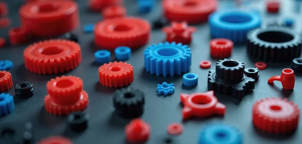
Injection moulding is an excellent process for consistency, repeatability and a high production rate. However, if an injection moulded component batch arrives with marks, distortion, incomplete features or inconsistent dimensions, there’s a problem. And this problem could affect thousands of individual parts.
Plus, it’s rarely just an aesthetic issue. A visible defect could delay sampling, increase scrap and rework costs, interfere with assembly, weaken the finished part, or create reliability problems once the component is in service.
The challenge is working out what caused the issue. Is it the material choice, component design, tool design or moulding process? In our experience, the answer often involves more than one of these factors.
At Talisman Group, we work with customers to consider part design, material selection, tooling and process control together. Below are some of the most common injection moulding defects and how they can be prevented.
What is injection moulding?
Injection moulding works by heating thermoplastic pellets until molten, then injecting that material into a custom-designed mould under high pressure. As the material cools and solidifies, it takes on the exact shape and detail of the cavity, giving you a finished component ready for assembly or further processing. Because the cycle repeats quickly and precisely, this process suits high-volume production where you need thousands of identical parts without variation.
Your design options are broad, too. Complex geometries, tight tolerances and intricate details are all achievable, from single-shot clear mouldings through to challenging technical over-mouldings. Materials range from standard thermoplastics, which soften and reset with heat, to thermoset options for applications where extra durability matters.
At Talisman Group, our press capabilities span 25 to 1,100 tonnes, covering everything from small precision components weighing just a few grams to large parts exceeding a square metre. Programmable controllers and automated auxiliary equipment keep every run consistent, so you can count on the same quality whether you need a handful of prototypes or a full production series.
Where do injection moulding defects come from?
As we mentioned above, most defects can be traced back to one or more of four areas:
- Part design, including wall thickness, ribs, bosses, corners and overall geometry
- Material selection and handling, including moisture content, flow properties and shrinkage behaviour
- Tool design, including gate position, venting, cooling channels and parting lines
- Moulding conditions, such as injection pressure, temperature, cooling time and holding pressure
It’s not always as simple as making one tweak to the production process. For example, if your component has a short shot, it might be tempting to increase the moulding pressure. However, too much pressure increases the risk of flash. Effective defect prevention is about considering the whole process holistically.
Flash?
Flash is a thin layer of excess plastic that appears around the parting line, ejector pins, inserts or other tool features.
It can make a part look untidy, create sharp edges, and add finishing work. In some cases, excess flash can also affect fit and assembly.
Flash may be caused by excessive injection pressure, high mould temperatures, worn or damaged tooling or insufficient clamp force.
To prevent flash, the mould must close correctly and remain in good condition. Process settings should be controlled carefully, with injection pressure and melt temperature kept within the correct operating range. The component should also be designed with realistic tolerances for the material and process.
Sink marks
Sink marks are shallow depressions on the surface of a moulded component. They commonly appear above thicker sections, ribs, bosses and areas where the plastic is slower to cool.
Although sink marks are often cosmetic-only, that may still be unacceptable according to your quality standards. They could also mean that the wall thickness is uneven.
Holding pressure, holding time and cooling time can also influence sink marks. However, process adjustments can only do so much if the design contains large variations in thickness.
The most effective way to prevent sink marks is through good part design. Wall thickness should remain as consistent as possible, while ribs and bosses should be designed to support the component without creating overly thick areas.
Voids
Voids are internal hollow spaces within the moulded part. Unlike sink marks, they may not always be visible from the outside.
They’re particularly concerning where a component needs to carry a load, remain pressure-tight or maintain reliable performance over time.
Voids usually form when thicker sections cool and shrink without enough material packing them out. They can also be associated with poor gate design, insufficient holding pressure or premature gate freeze-off.
Again, design is the most effective way to prevent voids. Use consistent wall thickness, design thicker features carefully and ensure the tool has suitable gate placement and cooling. Adjust holding pressure as needed, and account for load-bearing or pressure-tight aspects early in the design and process.
Short shots
A short shot occurs when molten material doesn’t completely fill the mould cavity. As a result, the finished component may be missing a section, have incomplete features or fail to form thin areas.
This is a clear functional defect. A short shot can prevent assembly, compromise the performance of the part, and result in immediate rejection.
Common causes include insufficient injection pressure, low melt temperature, poor venting, restricted flow paths, or a gate that is too small or poorly positioned.
Weld lines
Weld lines, sometimes called knit lines, form where two flows of molten plastic meet inside the mould. They may appear around holes, inserts, openings or areas where the material has to flow around a feature.
In some cases, weld lines are only visible marks. These may or may not be flagged as part of your quality control measures. In more serious cases, weld lines can represent weak points in the component, especially where the part is exposed to loading, pressure, impact, or repeated movement.
Flow lines and jetting
Flow lines are visible patterns, waves or streaks that follow the path of material through the mould. Jetting is a separate flow defect, where material enters the mould as a fast stream and starts to cool before it spreads evenly through the cavity.
These defects are usually cosmetic, but they can indicate inconsistent filling conditions or poor gate placement.
Flow lines may be caused by low melt temperature, slow injection speed, unsuitable gate design or sudden changes in wall thickness. Jetting is more likely where material enters the mould as a fast, free stream because of gate position, gate design or excessive injection speed.
Burn marks
Burn marks are brown, black or other ‘burn-coloured’ areas on the moulded part. They’re usually caused by trapped air or gasses overheating as the mould fills.
Of course, burn marks affect your part’s finished appearance. They could also indicate material degradation in the affected area.
Burn marks often happen when air gets trapped inside the mould because the vents are too small, blocked or poorly positioned. As the mould fills, that trapped air is compressed and overheats. High injection speeds, high melt temperatures and poor flow near the end of filling can make the problem worse.
Splay marks
Splay marks, sometimes called silver streaks, appear as fine lines or streaks across the surface of the part. Unlike flow lines, which follow the path of plastic as it moves through the mould, splay marks usually look like fine silver or white streaks spreading across the surface.
Splay marks often indicate moisture in the material, but they may also be caused by excessive shear, contamination or material degradation. (In contrast, flow lines are mainly caused by the material filling the mould.)
Many plastics commonly used in injection moulding, including nylon (PA), ABS, polycarbonate (PC), PET, PBT, acrylic (PMMA), and thermoplastic polyurethane (TPU), are hygroscopic (that is, they absorb moisture from the air. That’s why the correct material storage and drying processes are essential.
If the problem continues, the process may need to be reviewed for excessive temperature, injection speed or shear during filling.
Warpage
Warpage occurs when a component bends, twists, bows or distorts as it cools. It’s one of the most frustrating defects because a part can sometimes pass quality controls when first removed from the mould but later fail to fit during assembly.
Warpage naturally affects dimensional accuracy, sealing, fastening, clip engagement and the overall appearance.
It’s commonly caused by uneven cooling, inconsistent wall thickness, material shrinkage, fibre orientation or residual stress within the moulded part.
Delamination
Delamination occurs when layers of material separate at or near the surface of the component. The part may look as though it is peeling or flaking.
Although this results in an obvious cosmetic concern, it’s more than that. Delamination can also reduce the strength and durability of the finished part.
It may be caused by material contamination, moisture, incompatible materials, poor melt conditions, or degraded or contaminated regrind.
Reducing defect risk before production starts
If possible, the most cost-effective time to prevent injection moulding defects is before the tool is manufactured.
Early design-for-manufacture input helps your design team identify potential risks around wall thickness, rib design, gate placement, material flow, cooling, shrinkage and part ejection. This reduces the likelihood of expensive tool modifications, repeated sampling rounds, production delays and avoidable scrap.
It’s also important to select a material that suits the real demands of the application. Operating temperature, mechanical loads, electrical requirements, chemical exposure, flame performance, appearance and production volume can all influence the correct material and process decisions.
Need help preventing injection moulding defects?
Talisman Group works with customers from early design and material selection through to tooling, sampling, and ongoing production. Our ISO 9001-certified quality management system supports controlled processes, inspection, traceability, corrective action and continual improvement throughout production.
Whether you’re developing a new component or resolving an issue with an existing design, our team can help you reduce moulding risks and produce reliable, repeatable parts. Get in touch today to learn more about our design, tooling and injection moulding processes, or request a tailored quote.